Reactor Vent Line Connection to a Vent Header
In chemical and pharmaceutical plants, process vent header design is critical to ensure the safe handling of vapors, gases, and traces of condensables released from reactors.
Reactor vent lines must be connected to the process vent header in a way that prevents liquid backflow, avoids blockages, and ensures reliable operation under both normal and upset conditions.
In previous discussions on process safety, we analyzed the Safety Relief Valves vs Rupture Discs: Key Differences.
In this article, the focus shifts to vent header design, with particular attention to reactor tie-ins and recommended design approaches to prevent condensate backflow.
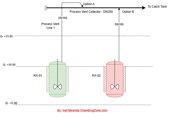
Fig. 1 – Technical diagram for vent header design: two reactors (RX-01 and RX-02) connected to a process vent collector (DN200), with vent lines DN100. Two tie-in options are shown for comparison.
The configuration of vent line tie-ins directly affects system reliability. A poorly designed connection may lead to condensate backflow, liquid traps, or vent line blockage—compromising process safety.
Importance of Vent Line Tie-In Design
A vent header is the main collector that gathers reactor vent streams and conveys them to a catch tank, scrubber, or flare.
If tie-ins are not correctly designed, condensate can enter the branch, forming liquid seals or backflow paths.
These issues reduce venting capacity and can undermine the protective function of the system.
Recommended Tie-In Configuration
Between the two alternatives shown in Fig. 1, the recommended choice is Option A – Top Tie-In.
Vent headers are designed to transport vapors safely. A top connection ensures that condensate formed in the header flows to the catch tank without entering the reactor vent line.
By contrast, a bottom tie-in (Option B) exposes the branch to liquid accumulating in the header. Condensate may fall into the branch, creating a liquid seal that reduces venting capacity and introduces a potential hazard.
Such configurations should be evaluated during HAZOP studies to assess potential flow restriction or condensate accumulation.
From a process safety perspective, Option A reduces the likelihood of condensate backflow and vent line blockage.
Tie-In Orientation and Design Details
Correct tie-in design is not limited to choosing a top connection: the orientation and execution of the branch are equally critical.
Fig. 2 – Example of vent header design with reactor RX-01 connected to a DN200 sloped header leading to the catch tank.
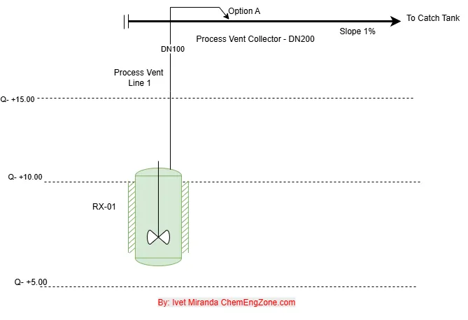
- Top tie-in (Option A)
When the branch connects from the top, aligned with the direction of flow, condensate remains at the bottom of the header and continues toward the catch tank. The branch is above the liquid film, preventing condensate re-entry. - Bottom tie-in (Option B)
A bottom connection exposes the branch opening to the liquid phase at the header base. Condensate can enter the branch, forming a liquid seal or backflow path. This configuration is therefore discouraged. - Branch orientation
The branch should be aligned with the header flow. Perpendicular connections create turbulence, stagnation zones, and potential liquid pockets, while a properly designed tee or weldolet ensures smooth gas entry.
In summary, a top tie-in, oriented in the flow direction, with a continuous slope from the reactor to the header is commonly adopted in industrial vent header systems to ensure reliable performance.
Normative and References
Several standards and guidelines emphasize the need for proper vent header design to avoid liquid accumulation and backflow:
- API 521 – Pressure-relieving and Depressuring Systems
- ASME B31.3 – Process Piping
- CCPS Guidelines for Pressure Relief and Effluent Handling Systems
- UK HSE – Safe Design of Large-scale Relief and Vent Systems
General design guidance from Perry’s Chemical Engineers’ Handbook (9th Edition, Chapter 23) recommends sloping vent headers toward a catch tank to prevent liquid accumulation, in line with API 521 and CCPS practice.
Conclusion
Correct tie-in orientation is not a minor detail. A top tie-in oriented in the direction of flow prevents condensate backflow, ensures self-draining lines, and increases system reliability.
Addressing these design considerations during the P&ID stage avoids costly redesigns and enhances overall process safety.
Ing. Ivet Miranda
⬆️ Back to TopVent Header Design Quiz
Why is a top tie-in generally preferred when connecting reactor vent lines to a process vent header?
Other Articles You May Find Useful
- Rupture Disc Positioning: Best Practices
- Safety Interlocks in Chemical Plants: P&ID Example
- Vacuum Tank Collapse: Hazards & Prevention
- Control Valve Leakage: What Process Engineers Should Know
- HAZOP Example: Material Compatibility Failure
FAQ
What is a vent header in chemical plants?
Vent header design refers to the engineering of the main collector pipe that gathers vapors from reactors or tanks and routes them safely to a catch tank, scrubber, or flare.
Why are top tie-ins preferred in vent header design?
Top tie-ins prevent condensate inside the header from flowing back into reactor vent lines. This ensures self-draining branches and reliable venting capacity..
How much slope should a vent header have?
Best practice is to design the header with a continuous slope toward the catch tank (typically 0.5–1%), ensuring that condensate drains naturally without creating liquid pockets.
What is the purpose of a catch tank in vent systems?
The catch tank collects and separates condensate carried in reactor vent lines before vapors are sent to treatment, preventing liquid carryover and protecting downstream equipment.