
Safety interlocks are widely used in industrial plants, but understanding them properly requires more than looking at the control logic alone.
To define an interlock correctly, engineers must read the process, identify the relevant operating conditions, and understand which action is needed when a deviation occurs.
In this article, a simplified P&ID is used to explain how that reasoning is developed in practice, with a practical example relevant to process engineering and process safety.
What Is a Safety Interlock?
A safety interlock is a protective logic used to move the process toward a safer condition when a predefined abnormal situation occurs.
In industrial plants, this logic is implemented in the control system, typically as ladder logic in a PLC (Programmable Logic Controller) or as equivalent logic in a DCS (Distributed Control System) or SIS (Safety Instrumented System). When a specific condition is detected, the system triggers a defined action in the field, such as closing a valve, stopping a pump, or isolating a source of energy.
Different interlocks may be triggered by similar abnormal conditions but require different actions, depending on how the process is configured. A temperature increase may require removal of heat input, while a high level condition may require stopping a transfer. The logic is implemented in the control system, but the engineering decision behind it comes from understanding how the deviation develops.
Safety Interlock Example: Heated Vessel P&ID
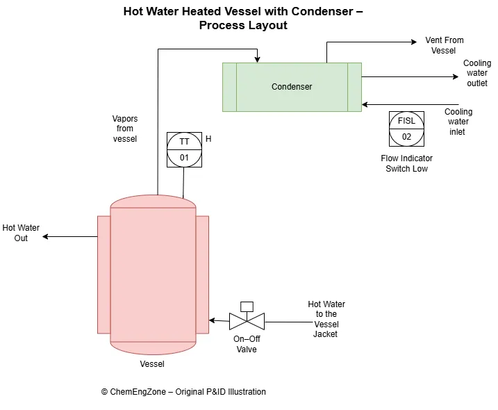
In the example shown, a vessel is heated by hot water through an on–off valve that controls the thermal input to the process.
Temperature inside the vessel is measured by TT-01 (Temperature Transmitter), with a high-temperature signal available as TTH-01 (Temperature Transmitter High). Vapors generated in the vessel are routed to a condenser, where cooling water is used to remove heat from the system.
The condenser operation depends on the availability of cooling water, which is monitored by FISL-02 (Flow Indicator Switch Low). This instrument detects low or no cooling water flow conditions.
From a process engineering point of view, the system behavior is straightforward. Heat input generates vapors, and proper condensation is required to keep the system under control.
Two main abnormal conditions can be identified:
- high temperature in the vessel
- loss of cooling water to the condenser
Both conditions can lead to a progressive increase in vapor generation or reduced condensation capacity.
For this reason, the interlock action is defined to act on the heating system.
When either high temperature (TTH-01) or low cooling water flow (FISL-02) is detected, the control logic in the DCS or PLC triggers the closure of the hot water on–off valve.
By removing the heat input, the system is prevented from further escalation.
Implementing Safety Interlocks in Ladder Logic
A safety interlock defined from process conditions is implemented in the control system as logic.
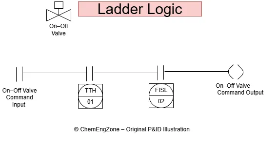
In PLC-based systems (Programmable Logic Controller), this logic is often represented using ladder logic. Ladder diagrams use a graphical structure similar to electrical circuits, where input signals are evaluated and combined to generate an output action.
In this representation:
- input signals correspond to process conditions (such as high temperature or low flow)
- the logic combines these conditions
- the output represents the command sent to the final element, such as an on–off valve
This is why terms such as command input and command output are used. The inputs represent the signals coming from the process, while the output represents the action generated by the control system.
The interlock defined from process conditions is implemented in the control system as logic.
In this example, the relevant signals are:
- TTH-01 (high temperature in the vessel)
- FISL-02 (low cooling water flow to the condenser)
These inputs are used in the control system (PLC or DCS) to generate a command that closes the on–off valve.
When one of these conditions is detected, the logic activates the valve shutdown, removing the heat input to the vessel and preventing further escalation.
When input signals are arranged in series in ladder logic, they represent an AND condition. This means that all conditions must be true for the output to be activated.
Conclusion
In this example, the safety interlock is defined by starting from the process and identifying where an action can effectively control the deviation.
The control logic is implemented in the PLC or DCS, but its effectiveness depends on the choice of the action and on where that action is applied.
A P&ID does not show the interlock logic itself, but it provides the information needed to understand how the process behaves and where a deviation can be stopped.
The interlock becomes meaningful only when the control action is consistent with the process behavior. If the action does not address the cause of the deviation, the logic may still exist, but it will not control the system in a reliable way.
⬆️ Back to TopSafety Interlock Quiz
In the heated vessel example, why is the interlock designed to close the hot water valve when high temperature or low cooling water flow is detected?
Other Articles You May Find Useful
- What Is HAZOP Analysis? Example and Template
- LOPA & SIL: Practical Examples
- Pressure Safety Valve vs Rupture Disc: Key Differences
- Rupture Disc Installation: Where to Place It
- Rupture Disc Activation: Near Miss or PS Event
- Control Valve Leak and System Isolation
- Vent Header Design: Safer Top Tie-In Layout
- HAZOP Example: Material Compatibility Failure
Useful External Resources
CCPS – Center for Chemical Process Safety
Authoritative resource on process safety, hazard evaluation, layers of protection, and risk reduction in industrial systems.
ISA – Safety Instrumented Systems (IEC 61511 Overview)
Clear overview of safety instrumented systems, interlocks, functional safety, and safety lifecycle concepts.
IEC – Functional Safety
General reference on functional safety principles relevant to interlock design and safety-related control functions.
FAQ
What defines a safety interlock in a process?
A safety interlock is defined by the action it performs when an abnormal condition occurs.
It is designed to move the process toward a safer state by acting on a specific part of the system, typically by removing a source of energy or stopping a transfer.
Can safety interlocks be implemented in a DCS or PLC?
Yes. Safety interlocks are implemented in control systems such as PLCs (Programmable Logic Controller) or DCS (Distributed Control System).
The logic is part of the control system, but its definition comes from process analysis. The signals used in the logic represent process conditions, and the output corresponds to the action applied to the system.
How are process conditions translated into interlock logic?
Process conditions such as high temperature or low flow are used as input signals in the control system.
These signals are evaluated by the logic, and when the defined condition is met, the system generates a command, such as closing a valve or stopping a pump.
What is the difference between an interlock and a control function?
A control function is used to maintain normal operation, for example by regulating temperature or flow.
An interlock is used when conditions move outside the normal operating range. Its purpose is not to control the process, but to prevent further escalation by forcing a predefined action.