Pressure Relief Devices: Engineering Selection Criteria
Have you ever had to decide the most appropriate pressure safety valve or rupture disc for a reactor?
In real chemical plants, this choice directly affects how a reactor behaves during an upset, how quickly pressure is relieved, and whether the system can stabilize after the event.
After a brief introduction to the essential theory, this article illustrates a practical reactor relief system example, comparing pressure safety valves, rupture discs, and combined RD+PSV configurations based on real engineering criteria.
Operating Principles
Pressure Safety Valve (PSV)
A pressure safety valve (PSV) is a mechanical pressure-relieving device that opens at a defined set pressure to protect equipment from overpressure. Most conventional PSVs are spring-loaded, although pilot-operated designs are also widely used.
Key characteristics:
• Modulated opening (reduces hydraulic shocks)
• Automatically recloses
• Requires periodic maintenance
• Susceptible to fouling, sticking, or leakage
• Can be equipped with position indicators, although rarely installed
Rupture Disc (RD)
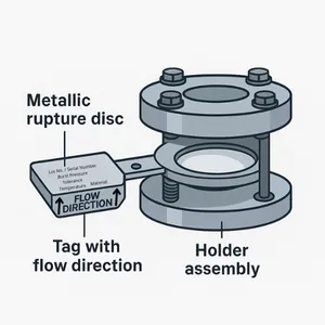
A calibrated membrane designed to open instantaneously once the burst pressure is exceeded.
Key characteristics:
• Immediate response
• Perfect tightness until it bursts
• No moving parts
• Cannot reclose
• Must be replaced after activation
• Easily integrated with burst sensors for immediate DCS signalling
To make these concepts clear, let’s start with a concrete example.
Selection Criteria
Automation and Opening Detection
A standard PSV does not provide an electrical opening signal. Newer valve models equipped with opening sensors are becoming available, but traditionally this feature has not been part of standard installations.
When additional opening-detection devices are installed, it is essential to verify that the valve’s functional reliability is not affected. The primary relief function must remain fully dependable, regardless of any accessory mounted on the PSV.
A rupture disc, on the other hand, can be equipped with a burst detector that generates an immediate and unambiguous signal.
If the plant requires event detection, the rupture disc becomes a competitive option.
Fluid Characteristics
• Clean, non-corrosive gases → PSV or RD (both can be suitable depending on tightness requirements or opening characteristics)
• Corrosive, sticky, or polymerizing fluids → RD or RD + PSV
• Need for absolute tightness → RD
Pressure Behaviour
• Operating pressure very close to the set point → PSV offers better stability (modulated opening, less chatter)
• Fast runaways or very rapid pressure dynamics → RD preferred
• Layout with significant backpressure → both PSV and RD require verification, because backpressure affects PSV capacity and also shifts the burst differential of a rupture disc.
Backpressure is often a system effect driven by vent header layout and tie-in configuration, as discussed in Vent Header Design: Why Top Tie-Ins Are Safer.
Maintenance
• PSV → requires periodic overhaul (mandatory in many industries)
• RD → no routine maintenance, but must be replaced after bursting
PSV vs Rupture Disc: Reactor Case Study
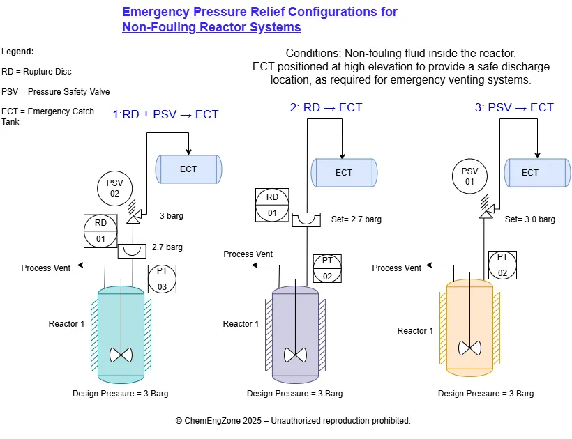
To make the comparison between rupture discs and safety valves more concrete, let’s look at a simple example based on three configurations commonly found in chemical plants.
In this case, the reactor’s emergency relief line is connected to an elevated Emergency Catch Tank (ECT), ensuring a fully open discharge path to the atmosphere.
The only device installed on the ECT vent is a flame arrestor, required when the external atmosphere may represent a potential ignition source.
Below are three typical configurations for the reactor’s emergency relief line:
• Rupture Disc + PSV → ECT
• Rupture Disc only → ECT
• PSV only → ECT
Each configuration responds to specific operational and engineering requirements, which we will analyse in detail in the following sections.
1. Rupture Disc + PSV → ECT
This configuration installs the two devices in series and is typically selected when the process fluid is expected to foul, corrode, or deposit solids that could compromise PSV performance over time.
In practice, the rupture disc acts as a physical barrier between the process and the valve, allowing the PSV to operate under controlled, relatively “clean” conditions.
Advantages of this configuration
- By isolating the PSV from the process, the rupture disc prevents corrosion, solidification, and sticking.
- Near-zero leakage is ensured until the disc bursts, eliminating PSV seat leakage.
- The PSV operates in a cleaner environment, increasing reliability and reducing spurious openings.
- Once the pressure drops below the blowdown, the PSV automatically recloses. This is a key advantage in scenarios where the system stabilizes quickly after the initial relief.
Operational and Design Implications
• Requires more space, additional flanges, and higher installation complexity.
• Long or elevated vent lines increase friction losses and static head.
As a result, when total backpressure approaches or exceeds ~10% of the PSV set pressure, the valve may open sluggishly, fail to achieve its rated capacity, or exhibit unstable behaviour such as chatter.
(According to API 520/521)
• When a rupture disc is installed upstream, the disc and its holder introduce additional inlet losses.
According to API 520, inlet line losses must remain <3% of the PSV set pressure to avoid delayed lift or instability.
• Liquid carryover into a gas-sized PSV can cause erratic opening or insufficient capacity. In such cases, the relief philosophy must be revised (knockout pot, liquid seal, liquid PSV, etc.).
• If the rupture disc ever bursts, the system must be shut down for replacement. For high-value continuous plants, where an unplanned shutdown results in major economic losses, this arrangement is used only when disc activation is considered extremely unlikely.
2. Rupture Disc Only → ECT
In this configuration the disc is the sole protection device. It offers extremely fast response, simplicity, and perfect tightness, but no modulation. Once it bursts, protection is total but irreversible.
Advantages of this configuration
• Instant response with no moving parts.
• No leakage up to the burst point.
• Easy integration of burst detection sensors.
• No routine maintenance.
Operational and Design Implications
• Once the disc bursts, the discharge is fully open and cannot be controlled; the reactor must be stopped.
• If pressure continues to rise after activation, there is no possibility to modulate the relief: the system remains fully open and the discharge cannot be regulated.
• No reclosing capability: once the disc has burst, the system stays fully open to the emergency line.
• If the rupture disc is installed too high or too far from the vessel, hydrostatic head and line losses can slow the pressure build-up at the disc, creating a time lag before it bursts.
3. Pressure Safety Valve (PSV) Only → ECT
This is the simplest solution and the most common where the process fluid is not particularly critical. The valve opens gradually, recloses, and allows the operation to continue after the event.
Advantages
• Controlled and progressive opening.
• Automatic reclosing.
• Ideal for slow contingencies, such as pool fires or gradually increasing pressures.
• Simple layout and low complexity.
Operational and Design Implications
• Potential leakage risk, especially with volatile or corrosive fluids.
• Sensitive to deposits, fouling, or sticky fluids.
• In many plants no opening signal is installed, making it difficult to know whether the PSV has operated.
Conclusion
Choosing between a Pressure Safety Valve and a rupture disc is an engineering decision, not a theoretical one.
Each solution — PSV, rupture disc, or a combined configuration — becomes correct only when it reflects the actual process behaviour, pressure dynamics, and plant layout.
There is no “best” device in absolute terms, only the right one for that specific operating scenario.
Ing. Ivet Miranda
PSV vs Rupture Disc – Engineering Quiz
In which situation is a rupture disc generally the most appropriate primary pressure relief device?
Other Articles You May Find Useful
• Rupture Disc Installation: Where to Place It
• Rupture Disc Activation: Near Miss or PS Event
• Vacuum Tank Collapse in Atmospheric Tanks
• What Is HAZOP Analysis? Example and Template
• Vent Header Design: Safer Top Tie-In Layout
Useful External Links
CCPS – Center for Chemical Process Safety
Authoritative guidance on process safety, risk analysis, hazard identification and PSM best practices.
US Chemical Safety Board (CSB)
Major accident reports, investigation videos, root cause analysis and lessons learned.
UK HSE – Process Safety Guidance
Technical guidance on process safety management, risk reduction, and regulatory compliance.
EU Seveso Directive – JRC
Official European Commission guidance for major accident prevention and Seveso site management.
OSHA – Process Safety Management (PSM)
Core regulatory framework for process safety in industrial plants.
IChemE Safety Centre
Advanced resources, guidance documents and industry case studies on chemical safety.
FAQ
What is the purpose of using a rupture disc instead of a PSV?
A rupture disc provides instantaneous opening, perfect tightness under normal operation and is immune to fouling.
It is preferred when extremely fast response is required, or when the process fluid could damage the internals of a PSV.
Often, rupture discs and PSVs are installed together in a combined configuration.
How often should pressure safety valves be inspected?
Inspection frequency depends on process conditions, equipment criticality and internal company standards.
In most industrial plants, PSVs are function-tested or serviced periodically to ensure proper operation and to prevent issues like fouling or leakage.
What determines backpressure in a PSV?
In most cases, PSV backpressure is a system effect, determined by downstream piping resistance, connected equipment, and the overall vent header configuration.
What determines backpressure for a rupture disc?
For rupture discs, backpressure is entirely a system effect.
It comes from downstream piping resistance, including line length, fittings, flame arresters, scrubbers, vent headers, and any condensate present.
Because a rupture disc does not modulate, backpressure does not create stability issues as it would for a PSV.
Instead, it directly affects the pressure differential required for rupture, meaning that high downstream pressure can delay disc activation or alter the effective burst behaviour.