

From Preliminary Sizing to Mechanical Rating
Sometimes in the plant, you will hear an engineer say: “What’s the big deal? Let’s just do a quick Q, U, and Delta T calculation to find out how much surface area we need.”
While this shortcut is highly simplified, engineering practice involves much more than just rigid theoretical derivations. In real-world process environments, many critical design decisions are analyzed simply through logic, common sense, and technical reasoning based on operational experience.
In this article, ChemEngZone wants to clarify exactly why our interactive Heat Exchanger Sizing Calculator is a valuable tool. It is not meant to replace heavy mechanical design suites, but it provides the essential preliminary baseline, giving you a quick, reliable order of magnitude so you know exactly where to start. Once you establish this thermodynamic anchor point, a massive array of physical, hydraulic, and safety constraints must be analyzed to move from a basic estimate to a functioning piece of industrial equipment.
The Value of a Preliminary Sizing Estimate
Every heat exchanger project begins with a set of process conditions, including stream compositions, target terminal temperatures, and mass flow rates. Before executing a detailed mechanical design, an engineer must solve the basic energy balance to determine the heat duty (\(Q\)) required by the process fluid:
By assuming a realistic, experience-based overall heat transfer coefficient U for the specific fluid pair, and calculating the Logarithmic Mean Temperature Difference (LMTD), you can solve for the ideal surface area:
This calculation is exactly what our Heat Exchanger Sizing Calculator accelerates. This initial number acts as a logical check. If the tool indicates a required area of 15 m2, technical reasoning tells you that a massive 150 m2 shell is completely oversized, while a compact 1 m2 unit will underperform. It could establish the scale of the equipment before you invest time into detailed drafting or software modeling.
Why Real Heat Exchanger Surface Areas Deviate from the Baseline
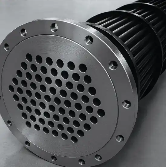
Comparing a final design to a preliminary estimate reveals why the physical area of an installed exchanger is almost always larger than the clean theoretical calculation.
Industrial Fouling Margins
Process fluids carry particulates, minerals, and trace corrosive elements. Over months of continuous operation, these compounds form a scale or rust layer on the tube walls. This fouling layer introduces an added thermal resistance that penalizes efficiency. To ensure the equipment can meet process specifications after long periods of service without requiring immediate cleaning shutdowns, engineers use their judgment to add a conservative 10% to 20% surface area margin over the clean theoretical baseline.
Geometric Flow Penalties and the F-Factor
The standard LMTD equation assumes a flawless, pure counter-current flow configuration. While compact plate heat exchangers mimic this behavior, standard industrial shell-and-tube exchangers often use multi-pass configurations where the flow pattern is mixed. To account for this geometric deviation, the temperature driving force must be penalized with a correction factor F :
Because F ≤ 1.0, any arrangement other than pure counter-current flow reduces the effective driving force and increases the physical surface area required. The main exception occurs during saturated steam condensation, where the isothermal phase change ensures a constant utility temperature, keeping F = 1.0 across all geometries. For a full breakdown of multi-pass configurations and shell-side routing, read our companion guide on Shell and Tube Heat Exchanger Design.
The Rating Loop: Transitioning to Real Geometry
Once the preliminary area gives you a starting point, the detailed engineering design takes over to verify if a real equipment geometry can actually satisfy that target. Instead of relying on an assumed U-value, the designer must look at what is physically happening inside the shell and the tubes.
The engineer starts by selecting a tentative mechanical layout, fixing parameters like tube diameters, total tube count, length, and the spacing of the baffles. This chosen physical geometry creates specific, real-world flow channels for both fluids.
Think about it: if you have more tubes inside the shell, the fluid side cross-sectional area changes. For a fixed mass flow rate, adding more parallel tubes means the fluid splits into more channels, which drops the velocity inside each single tube. Lower velocity means less turbulence, and less turbulence means the fluid film coefficient drops, decreasing the overall heat transfer efficiency. On the other hand, if you reduce the number of tubes to speed up the fluid and break the stagnant boundary layer, you will immediately face a massive increase in pressure drop. It is a continuous balance between thermal efficiency and hydraulic friction losses.
The exact same reasoning applies to the shell side, where the fluid path is even more complex. Segmental baffles force the fluid into a zigzag path across the tube bundle to maximize turbulence, but this redirection significantly increases friction losses.
When you combine these fluid film behaviors with the conductive resistance of the metal wall and the operational fouling factors, you realize why textbook equations scale everything to the outside surface area. Since a tube is a cylinder, the outside surface is physically larger than the inside surface. Because the heat transfers radially, the internal fluid resistance and internal fouling must be geometrically adjusted to match that larger outside plane.
If the actual surface area of the chosen equipment shell satisfies the area required by this calculated real-world behavior, the thermal design is validated. If not, the geometry must be adjusted iteratively—changing tube passes or shell lengths—until the physical layout safely satisfies the process requirements.
Plant Safety and Piping Constraints
A complete engineering analysis must look beyond thermal formulas and address the physical reality of the plant environment.
Overpressure Protection (Blocked-In Scenarios)
If cold liquid becomes trapped inside an exchanger shell or tube bundle due to the accidental closure of isolation valves while the opposing hot stream remains active, the trapped liquid will undergo rapid thermal expansion or vaporization. This blocked-in condition generates severe pressure spikes capable of causing catastrophic equipment rupture. Designing and installing a properly calibrated Pressure Safety Valve (PSV) or thermal relief valve is a mandatory safety step.
Cross-Contamination Boundaries
In sensitive applications—such as High Potent Active Pharmaceutical Ingredients (HPAPI), food processing, or highly toxic chemical services—a pinhole leak in a tube wall poses a severe contamination risk to the utility loop. Maintaining the chain of integrity requires upgrading the base mechanical configuration to double-wall tubes or double-tube-sheet designs to provide a physical containment barrier paired with early leak detection.
Orientation and Gravity Drainage
Physical space limitations and maintenance requirements heavily dictate equipment layout. For corrosive, fouling-prone, or high-purity services, a vertical exchanger orientation is highly preferred over a horizontal layout. A vertical configuration utilizes gravity to ensure complete drainage during system washdowns, preventing fluid holdup, dead-legs, and downstream cleaning bottlenecks.
Conclusion
Ultimately, designing a heat exchanger is not an easy task. There are numerous operational and physical factors that must be analyzed simultaneously. The journey begins with a preliminary estimation to understand the basic heat transfer surface area, but that number is just the first step. From that point forward, fluid dynamic constraints, velocity shifts, pressure drops, fouling layers, and process safety parameters take over, completely reshaping the final equipment layout.
⬆️ Back to TopHeat Exchanger Design Quiz
Why are segmental baffles installed in the shell side of a shell-and-tube heat exchanger?
Other Articles You May Find Useful
- What is Heat Transfer? Definition and Types
- Unit Operations in Chemical Engineering: Types and Examples
- Heat Exchanger Fouling and Rubby Formation
- Bernoulli’s Principle: Equation & Applications
- Fluid Dynamics Basics for Engineers
- Chemical Engineering Core Disciplines – A Practical Overview
- What Does a Chemical Engineer Do in Industrial Environments?
- What Is Chemical Engineering? Definition & Scope
Useful Engineering References
Thermopedia – Shell and Tube Heat Exchangers
Technical reference explaining shell-side flow, baffle configuration, heat transfer mechanisms, and design considerations for shell-and-tube exchangers.
Nuclear-Power.com – Shell and Tube Heat Exchanger
Engineering explanation of shell-and-tube exchanger design, including flow arrangement, baffles, and heat transfer behavior in real systems.
FAQ
What is a shell and tube heat exchanger used for?
A shell and tube heat exchanger is used to transfer heat between two fluids at different temperatures while keeping them physically separated. It is widely applied in chemical plants, refineries, power generation, and HVAC systems for heating, cooling, condensation, and evaporation duties.
What are the main types of shell and tube heat exchangers?
The main types differ based on the number of shell and tube passes (such as 1–1 or 1–2 configurations), the arrangement of baffles, and the mechanical construction (fixed tube sheet, U-tube, or floating head design). The selection depends on thermal duty, pressure, and maintenance requirements.
What factors influence shell and tube heat exchanger design?
Design depends on required heat duty, allowable pressure drop, fluid properties, temperature levels, fouling tendency, and mechanical constraints. The configuration of shell and tube passes also affects velocity, heat transfer coefficient, and thermal driving force.
What is the difference between a shell and tube heat exchanger and a shell and tube condenser?
A shell and tube condenser is a specific application of a shell and tube heat exchanger in which one fluid undergoes phase change from vapor to liquid. While the construction is similar, condensers are designed to handle latent heat transfer and two-phase flow conditions.