Corrosion Under Insulation (CUI) might be completely overlooked in a HAZOP if the analysis focuses only on the internal process conditions. External risks — like moisture infiltration or insulation failure — often require insights from maintenance and field inspections.
HAZOP Example: Water Piping Material Compatibility
When, as project engineers, we are assigned a task involving the installation of water lines — whether it’s industrial water, cooling tower water, or chilled water — our instinctive reaction is often one of relief:
“At least it’s not hazardous substances. There won’t be any major issues.”
This HAZOP example is drawn from a real-world situation . The aim is to show how a seemingly minor detail, if overlooked, can lead to significant risk scenarios — even when dealing with utilities that are generally perceived as “harmless.”
The following example is for illustrative purposes only. Every P&ID must be analyzed within its specific plant context, in a structured manner and according to the principles of a formalized HAZOP.
Distillation Shutdown Caused by a Missed Condenser Water Risk
Consider a process plant as shown in the figure below:
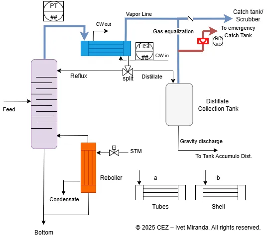
The following simplified diagram represents a distillation process section used to illustrate key HAZOP example considerations.
The diagram below is a simplified, illustrative representation of a distillation unit — adapted to support a targeted HAZOP discussion around the condenser section. It is not a full P&ID and omits several control elements that are not relevant to the specific deviations considered.
The system includes:
- A distillation column that separates feed into overhead and bottom fractions.
- A reboiler that provides thermal input to the column using a heating utility.
- A condenser, which cools the overhead vapors using a water-based utility.
- A three-way valve that splits the condensed liquid into:
- a reflux stream, returned to the column, and
- a distillate stream, sent to a collection tank via gravity.
- A vapor outlet line leading to a treatment or abatement system. A back-pressure element controls column pressure.
- A gas equalization line connects the condenser section to the collection tank to ensure pressure balance.
- An emergency relief line fitted with a rupture disc allows overpressure venting to a separate catch tank.
HAZOP Example: Focus on the Condenser
Now, we examine a small portion of the plant — specifically the condenser area — by applying selected HAZOP questions.
Note: This is not a full HAZOP study, but a simplified example intended for illustrative purposes only.
The goal is to show that, while guide words provide a structured method, meaningful risk identification depends on the team’s ability to connect deviations to real physical behaviors within the plant.
The image highlights two deviations:
- More Flow – Reflux
- Less Flow – Chilled Water to Condenser
For each case, plausible causes, consequences, existing safeguards, risk level, and potential technical recommendations have been considered.

The previous table summarizes a focused HAZOP example concerning the condenser section.
For each deviation, risk levels were determined based on a 5×5 matrix (likelihood vs. severity). The matrix is shown below to clarify how the “High” risk category was assigned.
Severity and risk levels are context-dependent.
Values shown here are plausible for illustrative purposes but must be verified against the specific plant design and safeguards.
During the HAZOP session, the team applied the guide word “less flow” to the reflux to column.
This triggered a discussion about possible causes of reduced reflux — a deviation that can severely affect distillation column stability.
The primary scenario identified was insufficient condensation in the overhead condenser, which limits the amount of liquid reflux returned to the column.
As the team traced the cause further upstream, a second deviation was formulated:
“Less flow” of chilled water to the condenser.
This sequence revealed a critical functional dependency:
- Less chilled water → Less condensation
- Less condensation → Less reflux to column
- Less reflux → Vapor accumulation at column top
- Vapor accumulation → High pressure and potential relief valve activation
In the case of reduced chilled water flow, one of the identified causes was leakage in the piping, which raised the question of whether the selected material was compatible with the service.
As a safeguard, the piping was confirmed to be carbon steel, a material deemed compatible with chilled water in terms of internal corrosion resistance.
However, the assessment did not account for external factors — particularly the risk of corrosion under insulation (CUI).
In systems using chilled water, pipelines are typically insulated. In humid environments, ambient moisture can condense on the outer surface of the insulation — especially when the pipe wall is colder than the dew point of the surrounding air.
This condensation can penetrate through damaged or aged insulation and accumulate on the outer surface of the pipe, leading to long-term external corrosion.
Unlike chilled water, which is chemically treated to prevent internal corrosion, ambient moisture contains oxygen, pollutants, and dissolved salts — making it far more aggressive toward carbon steel surfaces.
Corrosion under insulation (CUI)
This form of degradation, known as corrosion under insulation (CUI), is often hidden during normal operation and can result in severe failures — particularly when carbon steel is used externally without proper protection, such as specialized anti-corrosion coatings, sealed insulation with vapor barriers, drainage provisions, and periodic inspection access.
Issues like this could have been identified by maintenance personnel — particularly after commissioning, when the real-world impact of design decisions becomes more evident. Their direct experience with post-startup conditions offers a unique perspective, as they are the ones who ultimately deal with leaks, insulation failures, and unexpected degradation.
But it’s not only maintenance personnel who are essential in a PHA.
In this case, we focused on insulation issues, but for a PHA to be truly effective, many other people involved in the process must actively participate — such as process engineers, operations staff, instrumentation and control specialists, safety professionals, and sometimes even external contractors or project engineers.
In this case, although carbon steel appeared suitable on paper, the risk of external corrosion under insulation (CUI) was not considered.
As a result, what initially seemed like an acceptable material choice could have led not only to process instability — such as reduced condensation and column overpressure — but also to significant post-commissioning costs.
If the entire chilled water network had to be retrofitted due to premature corrosion, the financial and operational impact on the facility would have been substantial.
What to Do If a New Risk Emerges After a Completed PHA
Even when a Process Hazard Analysis (PHA) has been properly conducted, new information may emerge later — during commissioning, maintenance, or operation — that reveals an overlooked cause, deviation, or failure mechanism.
In such cases, action must be taken to reassess and control the associated risk.
Even when a Process Hazard Analysis (PHA) has been properly conducted, new information may emerge later — during commissioning, maintenance, or operation — that reveals an overlooked cause, deviation, or failure mechanism.
Here are the recommended steps:
1. Open a Management of Change (MoC)
Any new condition that could impact process safety must be addressed through a structured MoC. This ensures all technical and operational consequences are evaluated before any changes are implemented.
2. Reassess the PHA or Add an Addendum
If the new risk is significant, consider updating the existing HAZOP with an addendum or conducting a focused mini-HAZOP for the affected system. This helps maintain consistency and traceability.
3. Document the New Deviation
Clearly define the cause, potential consequences, and existing safeguards. Assign a risk ranking using the same method as in the original PHA, and record it as a formal deviation.
4. Update Operating and Maintenance Procedures
If needed, revise SOPs and maintenance instructions to reflect the updated understanding of the system. Ensure that actions related to the new risk are standardized in field practices.
5. Inform the Operations and Safety Teams
Communicate the new risk and any procedural updates to operators, technicians, and HSE personnel. Field awareness is critical for prevention and timely intervention.
6. Track the Change in the PSM System
Register the deviation and follow-up actions in your Process Safety Management system. This ensures compliance with internal policies and external regulations (e.g. OSHA PSM, Seveso III) and prepares the system for future audits or revalidations.
Operational Insights and Lessons Learned
A thorough Process Hazard Analysis (PHA) does not require any individual to know every technical detail or anticipate all failure modes in isolation — and this is precisely the principle behind the brainstorming technique used in HAZOP and other PHA methodologies.
Instead, what is required is the ability to ask the right questions, engage the right people, and observe the actual operating context.
Going into the field, speaking with maintenance and operations personnel, and reviewing the history of similar installations often provide more insight than design documents or P&IDs alone.
These practical sources uncover real-world issues — such as insulation damage, corrosion under insulation (CUI), fouling, mechanical fatigue, or undocumented modifications — that are seldom evident during the design phase.
A robust risk evaluation does not come from theoretical completeness, but from a collaborative process that connects design assumptions with operational reality.
Only by integrating operational feedback and lessons learned from comparable facilities can we properly anticipate deviations, assess realistic consequences, and define effective safeguards — ones that truly work in practice, not just on paper.
For those interested in exploring the HAZOP methodology in more detail, a clear and practical overview is available from the UK Health and Safety Executive (HSE). This official resource outlines the objectives, structure, and application of HAZOP studies in industrial settings, particularly under the COMAH framework, which is aligned with the Seveso III Directive.
Ing. Ivet Miranda
⬆️ Back to TopOther Articles You May Find Useful
• What Is HAZOP Analysis? Example and Template
• LOPA & SIL: Practical Examples
• Pressure Safety Valve vs Rupture Disc: Key Differences
• ATEX Zone Classification: Gas, Vapour & Mist
• Safety Interlocks: P&ID Example
FAQ
What does “material compatibility” mean in a PHA/HAZOP?
It’s the fitness of a material with both the internal service and the external environment. For insulated piping that means: internal fluid chemistry, temperature/pressure and external factors such as moisture ingress, insulation/jacketing details, coatings, supports, and expected maintenance.
When should material choice be treated as a HAZOP deviation?
When it can change a utility’s capacity or integrity. Typical nodes/devs:
Less flow – cooling water to condenser (due to external corrosion/partial blockage).
Loss of containment – insulated utility line (through-wall CUI).
Wrong material / inadequate protection – insulated piping.
How does CUI develop on insulated utility lines?
Moisture enters or condenses inside the insulation (damaged jacketing, unsealed joints, penetrations, wet–dry cycles). Oxygenated water sits against the pipe → external corrosion. Below-ambient services are vulnerable because they promote condensation; cyclic operation and poor drainage make it worse.
How do I reflect this in the HAZOP?
Document the chain: material/protection assumption → moisture ingress → reduced condensation → less reflux → column upset/overpressure. List existing safeguards (coatings, jacketing, alarms on utility flow) and actions (inspection plan, repair standard, design fixes, MoC for upgrades).