Bernoulli Principle and the Energy Balance in Fluid Flow
In Fluid Dynamics Basics for Engineers, streamlines, flow tubes, and the continuity equation are introduced to describe how fluid velocity varies along a pipe as a function of cross-sectional area.
This article introduces Bernoulli’s principle and its mathematical formulation to analyse fluid flow from an energy perspective, relating pressure, velocity, and elevation through a mechanical energy balance.
To apply this concept, a simplified flow model is considered. Two sections of the conduit, S1 and S2, are defined at heights h1 and h2 above a horizontal reference plane.
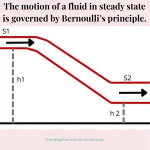
At each section the fluid is characterized by pressure (p1,p2) and velocity (v1,v2).
According to Bernoulli’s principle, the following relation applies:
p1 + 1/2 ρ v12 + ρ g h1 = p2 + 1/2 ρ v22 + ρ g h2
Where:
- p₁, p₂ = pressure at sections S₁ and S₂ [Pa]
- v₁, v₂ = velocity at sections S₁ and S₂ [m/s]
- h₁, h₂ = height of sections S₁ and S₂ above the reference plane [m]
- ρ = fluid density [kg/m³]
- g = gravitational acceleration (≈ 9.81 m/s²)
This relation illustrates how mechanical energy is conserved along a streamline. As the cross-sectional area decreases from S1 to S2, the fluid accelerates (v₂ > v₁), leading to a drop in pressure.
Since this relation holds between any two points along the same streamline, the quantity
is constant.
Mathematical formulation of Bernoulli’s principle
p + 1/2 ρ v2 + ρ g h =costant
Each term represents a mechanical energy contribution per unit volume of fluid.
Pressure term — p
This term represents the pressure energy, often referred to as flow work. It accounts for the mechanical work required to push the fluid through a control section. Although pressure is not an energy itself, it has the same units as energy density (J/m³) and therefore represents energy per unit volume available to drive the flow.
Kinetic energy term — 1/2 ρ v2
This term corresponds to the kinetic energy of the fluid associated with its velocity. It originates from the classical kinetic energy expression , normalized by the fluid volume. It quantifies the energy required to accelerate the fluid.
Potential energy term — ρgh
This term represents the gravitational potential energy of the fluid due to its elevation above a reference plane. It expresses the ability of the fluid to perform work as it moves downward in a gravitational field.
Hydrodynamic Paradox
In the following figure, two manometric measurements are taken along a horizontal pipe where the diameter decreases from section S1 to section S2.
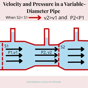
Although the pipe narrows from S₁ to S₂—causing the fluid velocity to increase—the manometric column measured at S₂ is lower than that at S₁. This indicates that the static pressure decreases as the flow accelerates.
At first glance, this behavior may appear counterintuitive: why should pressure drop where velocity increases?
According to Bernoulli’s principle, for a horizontal flow the elevation term remains constant. Consequently, any increase in kinetic energy associated with higher velocity must be balanced by a corresponding decrease in pressure energy. As the cross-sectional area decreases and velocity increases, the static pressure therefore necessarily drops.
This phenomenon is historically known as the hydrodynamic paradox. It highlights a fundamental concept in fluid dynamics: pressure cannot be interpreted in isolation, but must always be analyzed together with velocity and elevation within an energy balance framework.
The hydrodynamic paradox illustrates why intuition alone is insufficient when analyzing fluid flow. Engineers must instead rely on conservation principles to correctly interpret pressure measurements and flow behavior.
Limits of Bernoulli’s Equation
Although Bernoulli’s principle is fundamental in fluid dynamics, its equation is derived under simplifying assumptions: incompressible, inviscid, and steady flow along a streamline.
Bernoulli’s equation cannot be applied when the flow is unsteady, highly viscous, compressible at significant Mach numbers, or when strong energy interactions occur (such as pumps, turbines, or heat exchange with the surroundings). In these cases, additional terms must be introduced in the energy balance, or different models are required to describe the system correctly.
Example of Bernoulli’s Equation Applied to Pipe Flow
Problem
An ideal liquid flows through a horizontal pipe at an initial velocity of 40 cm/s in a section where the cross-sectional area is 3 cm².
Determine the velocity of the fluid when the cross-sectional area narrows to 2 cm².
Given:
v1 = 40 cm/s = 0.40 m/s
A1 = 3 cm² = 3 × 10⁻⁴ m²
A2 = 2 cm² = 2 × 10⁻⁴ m²
Continuity equation:
A1 × v1 = A2 × v2
Solving for v2:
v2 = (A1 / A2) × v1
v2 = (3 × 10⁻⁴ / 2 × 10⁻⁴) × 0.40
v2 = 1.5 × 0.40 = 0.60 m/s
While Bernoulli’s principle describes how mechanical energy is redistributed in ideal flows, real fluids are always affected by viscosity. When viscous dissipation is taken into account, pressure no longer remains constant along a pipe — even at constant velocity and geometry. This behaviour is described by the law of Poiseuille.
Applications of Bernoulli’s Principle
Bernoulli’s principle is widely used in engineering and physics. Classic applications include:
- Venturi meter – to measure the flow rate in a pipe using differential pressure.
- Orifice plate – a simple and compact device for measuring flow based on pressure drop.
- Pitot tube – used in aerodynamics and HVAC systems to measure fluid velocity.
- Aircraft wings (airfoils) – to explain lift generation due to pressure differences.
- Open tank outflow (Torricelli’s law) – to calculate the velocity of a fluid exiting a tank.
- Ejectors and jet pumps – devices that use fluid acceleration to entrain and transport another fluid.
- Carburetors – to mix fuel and air using pressure drop created by airflow.
- Flettner rotors / Magnus effect – rotational devices using pressure differences for propulsion.
- Industrial piping – for estimating pressure drops and designing efficient flow systems.
Conclusion
Bernoulli’s principle provides an energy-based interpretation of fluid flow, linking pressure, velocity, and elevation through mechanical energy conservation. This perspective remains fundamental for understanding real systems, even when ideal assumptions are not fully met.
Ing. Ivet Miranda
⬆️ Back to TopBernoulli’s Principle Quiz
In which situation can Bernoulli’s equation be correctly applied without additional correction terms?
Other Articles You May Find Useful
- First Law of Thermodynamics and Joule’s Experiment
- Second Law of Thermodynamics: PM 2nd Kind
- Fluid Dynamics Basics for Engineers
- Heat Transfer Basics for Engineers
- Unit Operations: A Practical Introduction for Engineers
- What Does a Chemical Engineer Do in Industrial Environments?
- Chemical Engineering Core Disciplines – A Practical Overview
FAQ
What is Bernoulli’s equation?
Bernoulli’s equation describes the conservation of energy in fluid flow. It shows how pressure, velocity, and elevation are related in a moving fluid.
What is Bernoulli effect?
The Bernoulli effect refers to the drop in fluid pressure that occurs when the flow speed increases — a key observation from Bernoulli’s principle.
Bernoulli’s law: what does it state?
Bernoulli’s law states that the total mechanical energy of the fluid remains constant along a streamline: pressure energy + kinetic energy + potential energy.
How does Bernoulli’s principle work?
Bernoulli’s principle works by balancing pressure, kinetic, and potential energy in a fluid. When one increases, at least one of the others must decrease.
Which uses Bernoulli’s principle?
Bernoulli’s principle is used in aircraft wing design, flow meters (like Venturi meters), carburetors, spray bottles, and even chimney ventilation.