Main Components of a Shell and Tube Heat Exchanger
This article is part of the Heat Transfer topic within Unit Operations.
If you are reviewing the fundamentals, you may want to start from the complete Heat Transfer overview.
A shell-and-tube heat exchanger consists of a cylindrical shell containing a bundle of parallel tubes. One fluid flows inside the tubes (tube side), while the second fluid circulates on the shell side, flowing across the tube bundle.
The separation between the two fluids is ensured by the tube sheet, which mechanically anchors the tubes and prevents cross-contamination. Inside the shell, segmental baffles are installed to redirect the flow across the tubes, increase turbulence, and enhance the shell-side heat transfer coefficient.
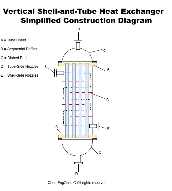
The simplified diagram above shows the principal construction elements of a vertical shell-and-tube heat exchanger. Segmental baffles force the shell-side fluid to follow a zigzag flow path, increasing cross-flow velocity and promoting higher external convective heat transfer.
How Fluid Flow Is Controlled Inside a Shell-and-Tube Heat Exchanger
Inside a shell-and-tube heat exchanger, heat transfer performance is strongly influenced by how the two fluids are forced to move through the equipment.
On the tube side, the fluid flows inside the parallel tubes. The flow is typically driven by pumps and is therefore classified as forced convection. Velocity is selected to balance heat transfer efficiency and pressure drop. Higher velocities increase the internal convective coefficient but also raise friction losses.
On the shell side, the situation is more complex. If the shell were empty, the fluid would tend to flow longitudinally along the tubes, resulting in poor cross-flow interaction and low heat transfer performance.
For this reason, segmental baffles are installed inside the shell. These baffles redirect the shell-side fluid across the tube bundle, forcing it to follow a zigzag path. This creates repeated cross-flow conditions over the tubes, increasing turbulence and significantly improving the external heat transfer coefficient.
However, this improvement comes at a cost: the redirection of flow increases shell-side pressure drop. As a result, baffle spacing and cut are critical design parameters that must balance thermal performance and hydraulic resistance.
Flow Arrangements and Tube Passes
In shell-and-tube heat exchangers, flow configuration is commonly described using a numerical notation such as 1–1 or 1–2. The first number indicates the number of shell passes, while the second represents the number of tube passes.
A 1–1 exchanger has one shell pass and one tube pass, meaning both fluids cross the exchanger once. A 1–2 exchanger maintains one shell pass but divides the tube-side flow into two passes by means of a partition in the channel head.
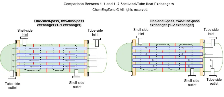
In a multi-pass configuration, the tube-side fluid reverses direction inside the channel head. This effectively increases fluid velocity without increasing exchanger length. Higher velocity improves the internal convective heat transfer coefficient but also increases pressure drop.
In a 1–1 exchanger, true countercurrent flow can be achieved if the inlets are arranged appropriately.
In contrast, 1–2 configurations produce a mixed flow pattern. While portions of the exchanger operate under countercurrent conditions, other sections approach parallel flow behavior.
Because of these flow patterns, the effective temperature driving force differs between configurations. This is why correction factors are required in thermal design calculations for multi-pass exchangers.
The selection between 1–1 and 1–2 configurations is therefore a balance between thermal performance and hydraulic constraints. Multi-pass arrangements increase tube-side velocity and heat transfer coefficient, but they also introduce higher pressure drop and modify the effective temperature driving force within the exchanger.
Conclusion
The number of shell and tube passes influences the hydraulic behavior of the exchanger and the distribution of temperature along its length.
Multi-pass configurations increase tube-side velocity and internal heat transfer coefficient, but they also lead to higher pressure drop and a more complex temperature profile.
The final configuration must therefore be selected based on process requirements, allowable pressure drop, and desired thermal performance.
Ing. Ivet Miranda
Shell-and-Tube Configuration Quiz
A process requires increased tube-side heat transfer without extending exchanger length. Which configuration is most appropriate?
Other Articles You May Find Useful
- What is Heat Transfer? Definition and Types
- Heat Exchanger Fouling and Rubby Formation
- The 4 Laws of Thermodynamics
- Work in Thermodynamics. PV Diagrams
- Second Law of Thermodynamics: PM 2nd Kind
FAQ
What is a shell and tube heat exchanger used for?
A shell and tube heat exchanger is used to transfer heat between two fluids at different temperatures while keeping them physically separated. It is widely applied in chemical plants, refineries, power generation, and HVAC systems for heating, cooling, condensation, and evaporation duties.
What are the main types of shell and tube heat exchangers?
The main types differ based on the number of shell and tube passes (such as 1–1 or 1–2 configurations), the arrangement of baffles, and the mechanical construction (fixed tube sheet, U-tube, or floating head design). The selection depends on thermal duty, pressure, and maintenance requirements.
What factors influence shell and tube heat exchanger design?
Design depends on required heat duty, allowable pressure drop, fluid properties, temperature levels, fouling tendency, and mechanical constraints. The configuration of shell and tube passes also affects velocity, heat transfer coefficient, and thermal driving force.
What is the difference between a shell and tube heat exchanger and a shell and tube condenser?
A shell and tube condenser is a specific application of a shell and tube heat exchanger in which one fluid undergoes phase change from vapor to liquid. While the construction is similar, condensers are designed to handle latent heat transfer and two-phase flow conditions.